Computer-aided design systems and the advancements in water treatment solutions.
These unique cad design tools have allowed our society to progress rapidly. There have been drastic improvements within the CAD world. CAD computer-aided design programs became commercially available in 1964 when large companies like IBM, GM, and Lockheed Martin began leveraging computerized graphical display systems. These foundational programs are still the basis for some of the most widely used programs.
To this day, 2D CAD is used regularly throughout multiple industries, including Water Treatment, Municipal, Food & Beverage, Commercial, and Pisciculture. While 3D CAD has many advantages over traditional 2D, it is essential to consider your product and its end user. All fabrication drawings, from structural to electrical, are read on 2D paper.
Architects and civil engineers use 2D to convey their ideas to cities, companies, and private parties. Electrical engineers create complex wiring diagrams in 2D only. Due to the clarity provided and adhering to standards followed worldwide.
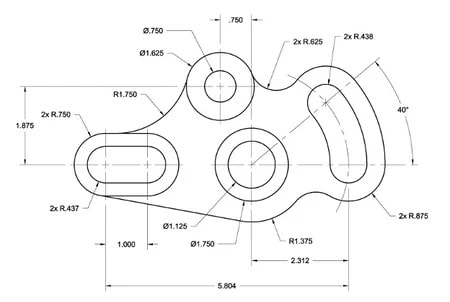
Figure: Example of a 2D CAD Drawing.
On the other hand, the 3D CAD design program is a young technology that has provided amazing breakthroughs in workflow increases and cost savings. 3D modeling became widely accessible in the late 1980s. It became a challenge that required engineers to rewire their brains to create models in the third dimension. 3D CAD software has two main categories:
- Parametric modeling
- Direct modeling
Direct modeling: grants the user flexibility by allowing them to define and capture geometry quickly without concentrating on dimensions. Direct modeling is perfect for prototyping, considering how agile the method is. A simple analogy would be to imagine working with modeling clay. Rather than measuring, you push and pull until you are satisfied with the geometry.
The downside to direct modeling in the professional world is that automation is nearly non-existent. The computer does not store changes made during the project. The model is simply a constrained geometric concept. If multiple changes are needed, they are not referencing one another, which could be time-consuming.
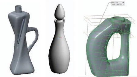
Figure: Examples of Direct Modeling. Note that these are dimensionless print models.
Parametric modeling: involves designing using features and constraints, which creates a design tree of features stacked upon each other. This type of modeling expresses the engineer’s design intent, a specification of how a part should appear and function.
Parametric is much more precise than direct modeling. Parametric modeling requires setting boundaries and parameters (hence, parametric) to create a product that easily allows integration into manufacturing. Although the regulation of dimensions is helpful in most cases, there are some downsides.
Parametric modeling strictly requires defining values. Any changes made to the model are not the first choice for prototyping. Since features such as extrusions or cuts linearly reference one another. Changes to a finalized project could be a recipe for error messages.
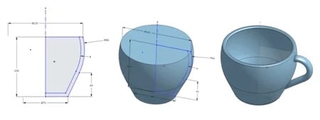
Figure: Example of Parametric Modeling. Note that each detail is dimensioned, resulting in a precise model.
When bringing a model to production stages, parametric takes the cake without question. Not only are dimensions critical to producing repeatable products. But some CAD software provides integrated CAM packages to take it further.
CAM, or Computer Aided Manufacturing: is commonplace in today’s world. Simply put, CAM is software that automates manufacturing processes by generating tool paths for a machine to output raw material. So, combined with the dimensions provided by parametric modeling, CAM is a step that naturally follows.
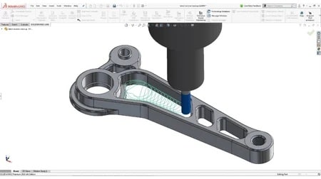
Figure: Example of the SolidWorks CAM package. An image of a CNC tool path and tool.
DeLoach Industries, we leverage the capabilities of programs such as SolidWorks and AutoCAD to provide quality products to our customers. Flexible between 2D CAD and 3D Parametric CAD can reduce project time, errors, and unnecessary costs. Contact our cad designers online at deloachindustries.com, or call us at (941) 371-4995.
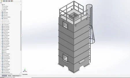
Figure: Example of Parametric Modeling at DeLoach Industries. Note: the design tree is on the left side of the screen.
At DeLoach Industries, we take pride in being at the forefront of cutting-edge water treatment solutions. Our services encompass a wide range of technologies, from water decarbonation and decarbonation systems to state-of-the-art artificial intelligence integrated into water treatment processes. We specialize in advanced decarbonators and aeration systems that effectively remove unwanted gases, ensuring high-quality water output for various industries. Our expertise extends to cogeneration systems and steam processes, optimizing energy efficiency and sustainability. With a dedicated focus on decarbonation and degasification, we are committed to delivering innovative solutions that surpass expectations, setting new industry standards, and safeguarding the environment for a sustainable future.


