In water treatment systems it is often important to measure the rate at which water is flowing through the system. Data from flow measurement devices can be used to control chemical dosing, set pump speeds, control filter loading rates, inform maintenance programs, and other tasks necessary for the operation of a water treatment facility or on key components such as Degasification and Decarbonation systems or Biological Odor Control Systems. As with most types of instrumentation, there is an array of technologies that can be used for the task, each one with various strengths and optimal applications. For modern electronically controlled systems, the most common types of flow sensors used are axial turbine flowmeters, paddlewheel flowmeters, differential pressure/orifice plate flow transducers, and magnetic flowmeters. This article will briefly discuss the technology and features of each of these types.

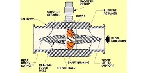
A turbine flow meter,
consists of a tube that contains supports to hold a multi-bladed metal turbine in the center. The turbine is designed to have close clearance to the walls of the tubing such that nearly all of the water is made to flow through the turbine blades as it travels through the pipe. The turbine is supported on finely finished bearings so that the turbine will spin freely even under very low flows. As the turbine spins, a magnetic pickup located outside of the flowmeter housing is used to sense the tips of the turbine blade spinning past the pickup. An amplifier/transmitter is then used to amplify the pulses and either transmit them directly or convert the pulse frequency into an analog signal that is then sent to a programmable controller for further use elsewhere in the system. One advantage of a turbine flowmeter is that the electronics are separated from the fluid path. The magnetic pickup is the only electronic component, and it is installed outside of the turbine housing, reading the presence of the turbine blade tips through the wall of the sensor body. In clean water applications, this can be advantageous because the magnetic pickup can be replaced if needed without removing the turbine from service. However, the turbine itself covers most of the pipe area and creates back pressure in the system, requiring increased pumping energy to move a given amount of water. In Industrial Water Treatment or Filtration Treatment, turbines can also easily become fouled or jammed if they are used to measure water or other fluids with entrained solids, algae or bacteria cultures which cause significant accumulation, or corrosive chemical components that can degrade the turbine bearings.
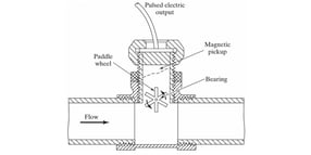
A related flow measurement technology is the paddle-wheel flowmeter. In a paddle-wheel sensor, the basic principle is similar to the turbine, except that the rotating element is in the form of a paddle wheel that sits at the flow boundary of the pipeline. In this sensor type, only a small portion of the water flow interacts with the paddlewheel. In addition, the axle and bearings are less exposed to the flow medium which makes the sensor less susceptible to fouling. Since there is less mechanical obstruction to the flow path, the paddlewheel also imparts less back pressure to the system. However, since a smaller portion of the fluid flow is interacting with the paddle, a flow measurement from this type of sensor has more inherent uncertainty to the measurement.

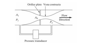
A third type of pressure measurement device is the differential pressure or orifice plate flow transducer. In a differential pressure flow transducer, a plate is inserted between two flanges in the pipework. The plate will contain a single, or sometimes multiple holes that the water or other flow medium is forced through. This will cause an increase in pressure upstream of the orifice plate and a decrease in pressure downstream of the orifice plate. A differential pressure transducer is then used to measure the difference between the high-pressure and low-pressure sides. This pressure reading is then used to calculate the flow rate based on standard equations that describe flow through sharp-edged orifices. The orifice plate flow transducer has the advantage of containing no moving parts. In addition, the actual measurement device is the differential pressure transducer, which is kept outside of the pipeline and can be removed, replaced, or maintained without stopping the flow or opening up the pipe. In a water treatment system, a properly sized orifice plate measurement system can be in service for years, if not decades before it needs to be replaced. The orifice plate still has the side effect of increased back-pressure on the system due to the flow restriction that is inherent in its design.

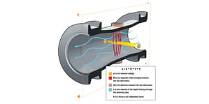
A fourth type of flow measurement is the magnetic flowmeter. This type of flow meter is often used for corrosive environments, high solids or abrasive water, and in many types of odor control scrubbers or air emission treatment systems. This device imparts no flow restriction and also has no moving parts. While it is the most technologically complex of the sensor types discussed here, and often the most expensive, the ease of maintenance and benefits to system efficiency make it an increasingly popular option for flow measurement. Conductive liquids moving through a magnetic field will generate a voltage potential in proportion to the flow velocity. In a magnetic flowmeter, an electromagnet or permanent magnet is used to create a magnetic field across the diameter of the pipe. A pair of electrodes are exposed to the flow area at 90 degrees to the magnetic field. The magnetic field and the electrodes are also set at 90 degrees to the water flow direction. As the water flows, the induced electrical current is picked up by the electrodes. This electrical current is measured by sensor electronics, and the flow rate is calculated based on the strength of the signal combined with the conductivity of the water and the diameter of the pipe. These measurements are highly accurate, and since there is nothing to impede the fluid flow, a magnetic flow meter adds no back-pressure to the system. In addition, most magnetic flowmeters can also output other data about the water such as conductivity, temperature, or accumulated flow over time.
Like most engineering decisions, the choice of flow measurement systems will always be some sort of trade-off. At DeLoach Industries our in-house team of experts and engineers work with customers to determine and select the specific flow technology to achieve the performance objectives. There is no perfect measurement technology, but one can often make an optimal choice for a specific system under a set of parameters. The magnetic flowmeter is accurate and non-restricting but involves significant upfront costs. The orifice plate transducer has a long life and simple maintenance but will add significant back-pressure to the system. The turbine and paddlewheel sensors have moving parts but are inexpensive. Understanding your own project goals and constraints along with the technologies available is the best way to make an optimal informed decision for your system. If you have any questions or would like to learn more contact the professionals at DeLoach Industries, Inc. at (941) 371-4995.


