Understanding Degasification and Decarbonation
In industrial and municipal water treatment systems, controlling dissolved gas levels is crucial for maintaining optimal performance, ensuring safety, and ensuring compliance. The term “Degasification” (or “Decarbonation”) refers to the process of removing unwanted gases such as hydrogen sulfide (H₂S), carbon dioxide (CO₂), and oxygen (O₂) from water.
While both processes share the same purpose of gas removal, the terminology changes based on the type of gas being targeted:
Decarbonation is typically used when removing carbon dioxide (CO₂).
- Degasification most often refers to the removal of hydrogen sulfide (H₂S) or other dissolved gases.
These processes are a critical step in water treatment, especially when preparing water for reverse osmosis (RO), boiler feed systems, or industrial reuse applications.
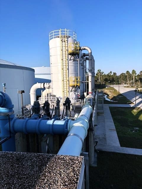
How Degasification Works
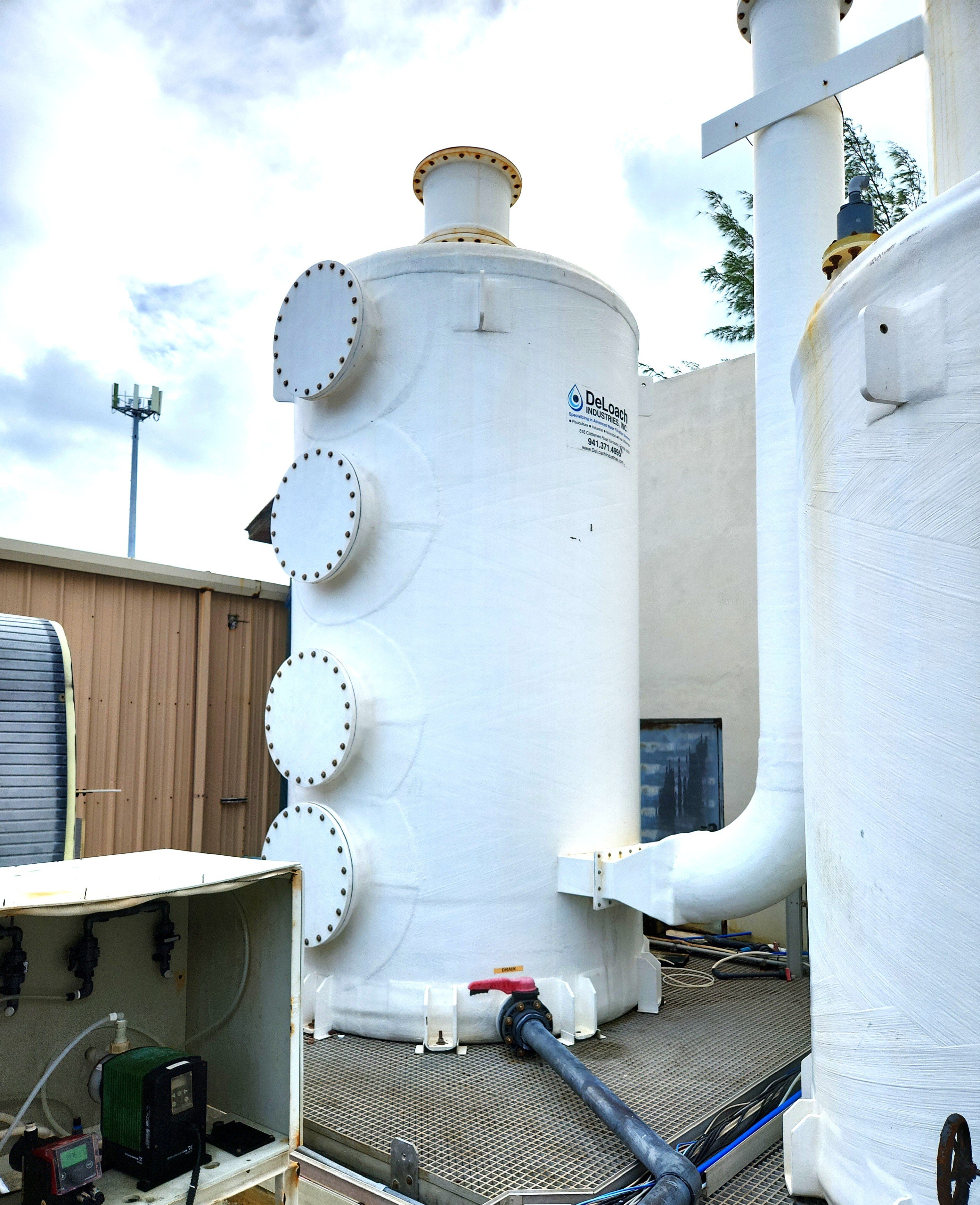
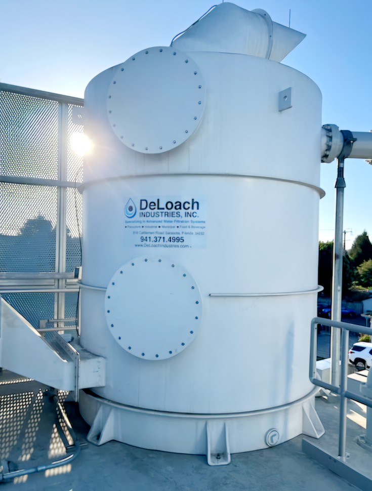
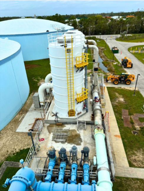
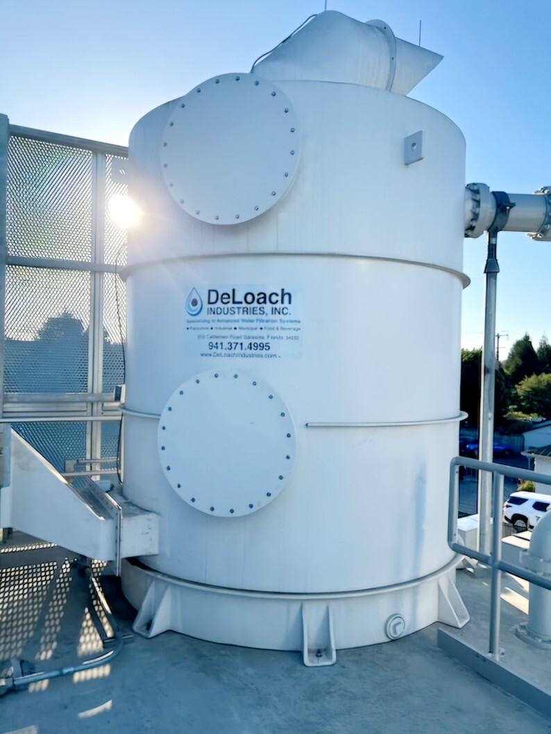
Degasification operates on the principle of transferring gases from water into the air. By forcing air through the water stream inside a degasification or decarbonation tower, the system promotes mass transfer, allowing the unwanted gases to escape.
Key factors influencing degasification efficiency
- Inlet Water Flow Rate: Higher flow rates require larger towers or more efficient packing media.
- Water Temperature: Warmer water releases gases more readily.
- Ambient Air Temperature: Impacts air density and transfer rate.
- Gas Concentration: Measured in ppm, ppb, or mg/L, this determines the tower’s design and airflow volume.
- Desired Effluent Levels: Defines the level of purity required for downstream applications.
Understanding these variables enables engineers to design a customized degasification system that meets stringent quality standards. For example, systems treating well water high in hydrogen sulfide must maintain consistent airflow and contact time to ensure complete removal of the gas.
To learn more about custom-engineered degasification systems, visit DeLoach Industries.
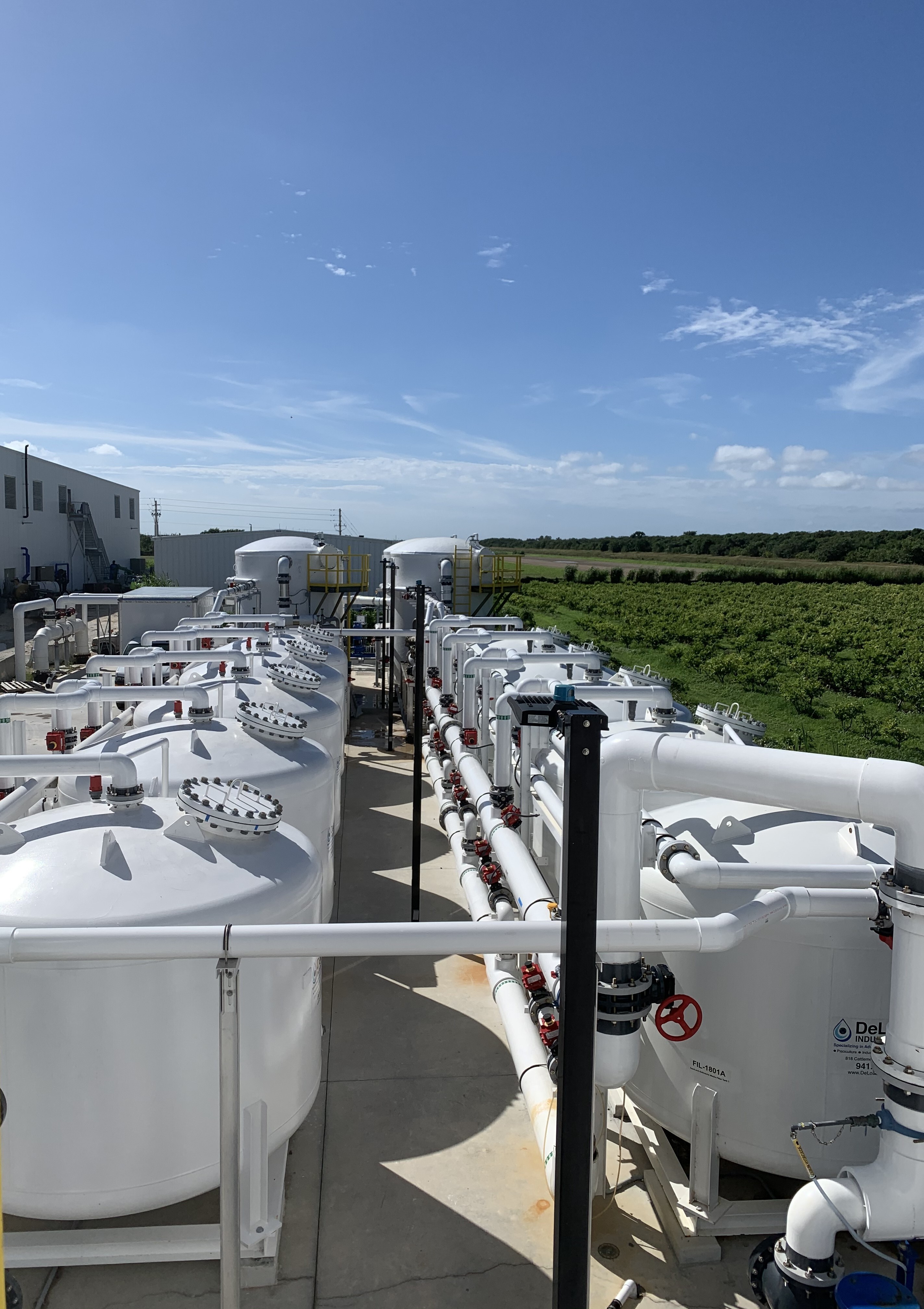
Applications: Reverse Osmosis and Membrane Filtration
Degasification is often integrated after Reverse Osmosis (RO) or membrane filtration to remove residual gases that pass through the membrane, such as H₂S and CO₂.
- Reducing Chlorine Demand
By eliminating these gases before chlorination, operators can significantly reduce chlorine consumption, improving disinfection efficiency and minimizing chemical costs.
- Improving Total Suspended Solids (TSS) Levels
Removing dissolved gases also enhances TSS performance, resulting in clearer, higher-quality permeate.
- Adjusting pH Without Chemicals
When CO₂ is removed, the pH naturally rises, helping stabilize the water without the need for caustic chemicals or lime, making degasification an eco-friendly solution for optimizing water treatment.
For a deeper dive into membrane treatment post-processes, explore DeLoach Industries’ water treatment solutions.
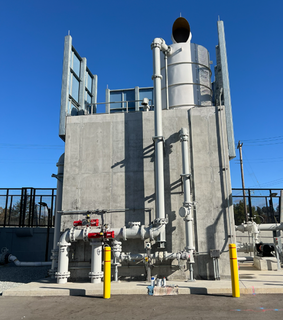
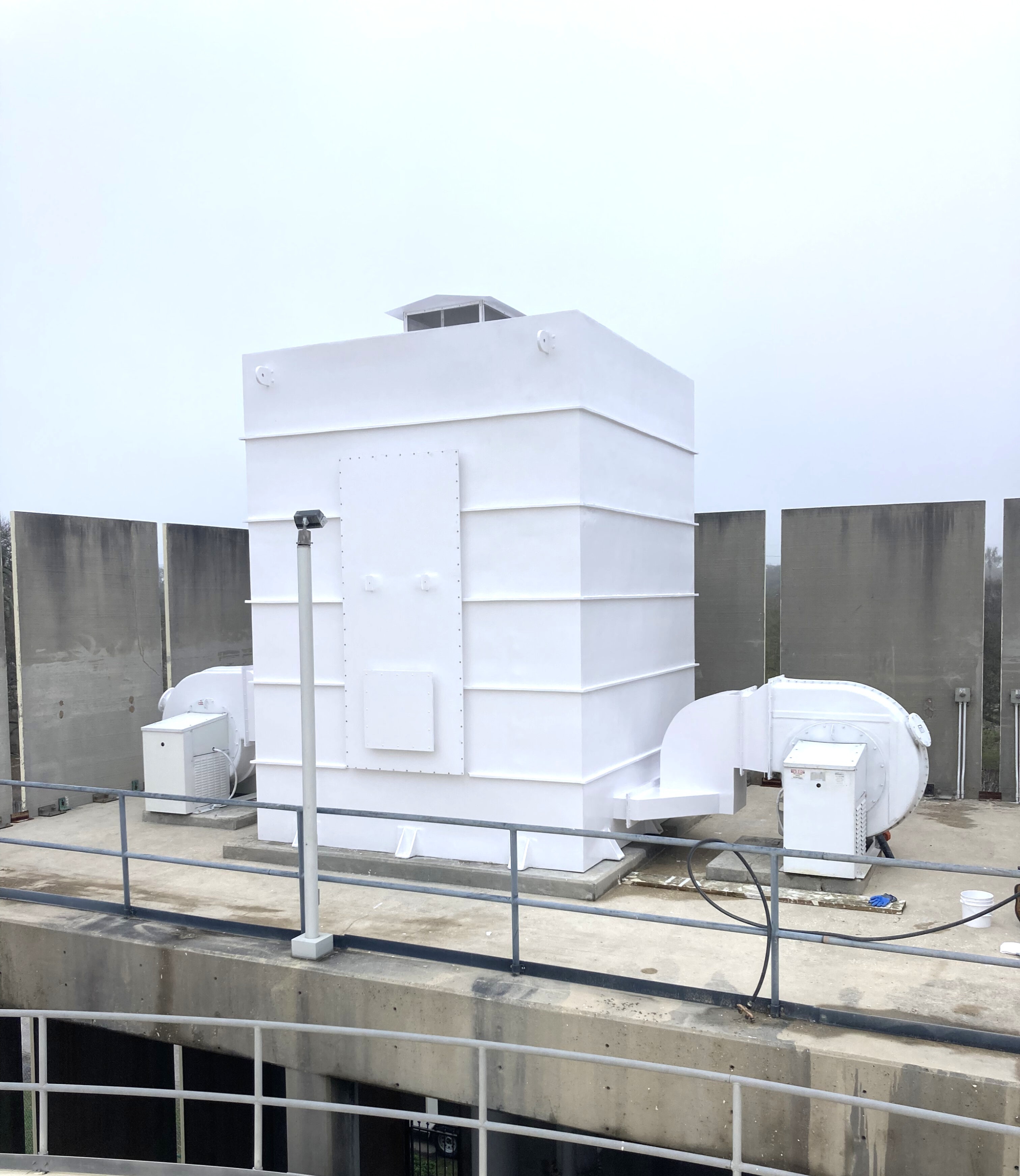
Managing Off-Gas and Odor Control
In some cases, the air discharged from a degasification or decarbonation tower can contain elevated H₂S levels, creating odor nuisances or even health and safety hazards for nearby personnel.
- Why Off-Gas Treatment Is Essential
Hydrogen sulfide, when combined with moisture, forms sulfuric acid, which corrodes nearby equipment and building materials. This makes off-gas treatment essential in steam processes, boiler feed systems, and industrial wastewater applications.
To mitigate emissions, facilities often install air scrubbers or odor control systems directly onto the off-gas line. These scrubbers use chemical or biological media to neutralize odors and capture harmful gases before release.
DeLoach Industries offers custom-engineered odor control and degasification solutions that integrate seamlessly with your existing treatment systems. Learn more about industrial water treatment technologies at www.deloachindustries.com.
The Economic and Environmental Benefits of Degasification
Degasification systems are not only effective, they’re also highly economical compared to chemical treatment methods.
Some key advantages include:
- Reduced chemical usage and maintenance costs
- Extended equipment life by preventing corrosion
- Improved water quality consistency
- Compliance with EPA and OSHA air quality standards
In municipal systems, this can translate into lower operational costs and enhanced environmental performance, especially when paired with other sustainable technologies, such as odor-control scrubbers and biotrickling filters.
Partner with DeLoach Industries for Advanced Water Treatment Solutions
For over 65 years, DeLoach Industries has been a trusted leader in designing and manufacturing custom degasification, decarbonation, and odor control systems for industrial and municipal clients worldwide.
Whether you need to remove hydrogen sulfide, naturally raise pH levels, or enhance the performance of your reverse osmosis system, our team can design a customized solution that meets your exact specifications.
Contact DeLoach Industries today at (941) 371-4995 to request a quote or speak with a water treatment expert.