In water treatment, it is often required to remove small particulate matter from the raw water.
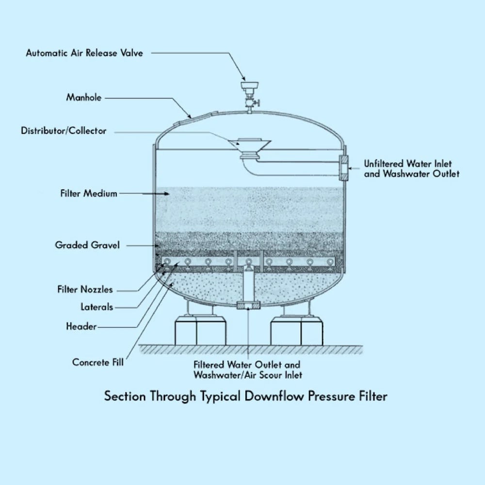
One of the most cost-effective ways to accomplish this is with a pressure filter. Sometimes referred to as “sand filters,” a pressure filter consists of a rigid filter vessel capable of withstanding internal pressure, combined with pipework to distribute and collect water and one or multiple types of filter media. Pressure filters are commonly used in municipal water systems, industrial facilities, residential well water systems, and swimming pools. Typical pressure filter construction is shown below:
At the top of the filter vessel, a distributor is used to break up and distribute the water flow so that there are no concentrated flow jets that stir up the media bed. Inflow distributors are usually oriented to direct flow at the top of the vessel to disperse the flow further. Below the distributor is the primary filter bed. The filter bed contains fine-grained media, most often sand, including crushed anthracite coal, activated charcoal, garnet, or other granular bulk products. The media bed is the thickest layer in the filter vessel and is the region that does the actual filtering of the water or other fluid. Below the media bed will be one or more support layers. These will usually be larger-sized gravel that is chosen to support the filter bed while allowing high flow through the support layer and into the outflow header. The outflow header can take several forms but is often composed of a large central pipe with multiple smaller pipes or “laterals” attached. The laterals are slotted or perforated. This allows the pressurized water to flow into the laterals and out through the outflow header into the downstream components of the water treatment system.
Read More
Topics:
particulate matter,
filters,
Pressure filter,
Sand filters,
Filter Media,
municipal water systems,
industrial facilities,
residential well water systems,
greensand,
DeLoach Industries, Inc.,
backwash,
automated control systems,
actuated valves,
pump controls
One issue that I run into relatively often with new technicians, or with some non-technical project managers is confusion over pipe sizing.
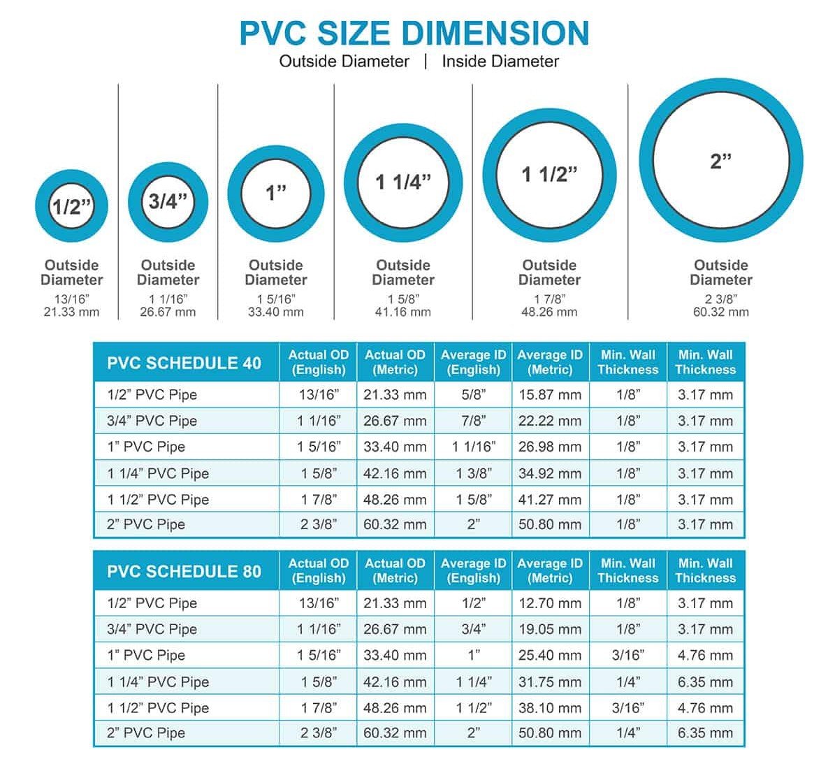
A typical example looks like this: I ask a new technician-in-training to get me a count of the 1-inch pipe that we have in storage. I take the info, and then later find out that what the trainee inventoried was the 3/4-inch pipe. The reason for this confusion lies in the way that pipe sizes are named. The 1-inch, 3-inch, 6-inch, etc. pipe designations are closer to names than sizes. This is because pipe sizing goes by a nominal size standard which is somewhat non-intuitive.
For many people, if they are asked to locate a pipe of a given size, 3-1/2” for example, they will take a tape measure and instinctually measure the outside diameter of the pipe, which will lead them to an incorrect identification. This has to do with the sizing conventions for pipes. Pipes are sized using a nominal pipe size (NPS) designation, and a pipe schedule (SCH) to fully define the size. The nominal size refers only to the approximate inside diameter, and the schedule refers to the wall thickness of the pipe. Because of this, the inner and outer dimensions of a pipe do not directly align with the “name” of the pipe size
Read More
Topics:
PVC,
Pipe Size,
Schedule 40,
Schedule 80
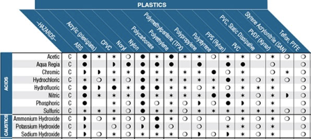
In process control systems, it is often required to handle fluids that have a harsh chemical nature. In these cases, it is necessary to be aware of material-chemical compatibility. Chemical compatibility is a general term referring to the way a specific chemical interacts with a specific material. This information is taken into consideration when selecting materials for construction for tanks, valves, pipework, tubing, and other devices that may encounter harsh chemicals. Common chemical types that are used in process systems are acids, bases, corrosives and oxidizers, and hydrocarbons. Typical chemical-resistant materials include natural and synthetic rubbers, vinyl polymers, fluoropolymers, and stainless steel. In order to determine which materials are compatible with certain chemicals, a chemical compatibility chart is often used. A chemical compatibility chart contains tabulated data about how a given material interacts with a given chemical.
Often, the manufacturer of the equipment or material in question will have their own compatibility chart for their specific goods. Most compatibility charts will have the same type of information. Materials will be categorized along one axis of the table, with fluids or gasses categorized along the other axis. At the intersection of a material with a fluid, you will find an indication of the level of compatibility. Some charts will use an A-F categorization, others may use a more graphical style. Most charts will be accompanied by a key or guide that explains how to use the table. There may also be multiple concentration levels and temperature ranges for a given fluid in cases where the distinction makes a difference with compatibility.
Read More
Topics:
degasification,
pH levels of water,
water treatment,
advanced treatment solutions,
hydrogen sulfide (H2S),
pH levels,
caustic,
Decarbonation,
decarbonator,
degasifier,
Deagasification
In water treatment systems it is often important to measure the rate at which water is flowing through the system. Data from flow measurement devices can be used to control chemical dosing, set pump speeds, control filter loading rates, inform maintenance programs, and other tasks necessary for the operation of a water treatment facility or on key components such as Degasification and Decarbonation systems or Biological Odor Control Systems. As with most types of instrumentation, there is an array of technologies that can be used for the task, each one with various strengths and optimal applications. For modern electronically controlled systems, the most common types of flow sensors used are axial turbine flowmeters, paddlewheel flowmeters, differential pressure/orifice plate flow transducers, and magnetic flowmeters. This article will briefly discuss the technology and features of each of these types.
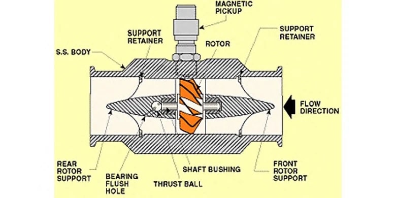
A turbine flow meter,
consists of a tube that contains supports to hold a multi-bladed metal turbine in the center. The turbine is designed to have close clearance to the walls of the tubing such that nearly all of the water is made to flow through the turbine blades as it travels through the pipe. The turbine is supported on finely finished bearings so that the turbine will spin freely even under very low flows. As the turbine spins, a magnetic pickup located outside of the flowmeter housing is used to sense the tips of the turbine blade spinning past the pickup. An amplifier/transmitter is then used to amplify the pulses and either transmit them directly or convert the pulse frequency into an analog signal that is then sent to a programmable controller for further use elsewhere in the system. One advantage of a turbine flowmeter is that the electronics are separated from the fluid path. The magnetic pickup is the only electronic component, and it is installed outside of the turbine housing, reading the presence of the turbine blade tips through the wall of the sensor body. In clean water applications, this can be advantageous because the magnetic pickup can be replaced if needed without removing the turbine from service. However, the turbine itself covers most of the pipe area and creates back pressure in the system, requiring increased pumping energy to move a given amount of water. In Industrial Water Treatment or Filtration Treatment, turbines can also easily become fouled or jammed if they are used to measure water or other fluids with entrained solids, algae or bacteria cultures which cause significant accumulation, or corrosive chemical components that can degrade the turbine bearings.
Read More
Topics:
water quality,
water treatment,
advanced treatment solutions,
About DeLoach Industries,
water plant,
pumps,
Alkalinity,
Safe drinking water,
wastewater,
Recycling,
pharmaceutical water,
Aqua Farming,
Aquaculture,
Pipe Size,
municipal water systems,
industrial facilities,
DeLoach Industries, Inc.,
actuated valves,
pump controls,
Drinking Water,
Clean Water,
Water Test,
Water Test Kit,
DeLoach Industries,
civil engineers
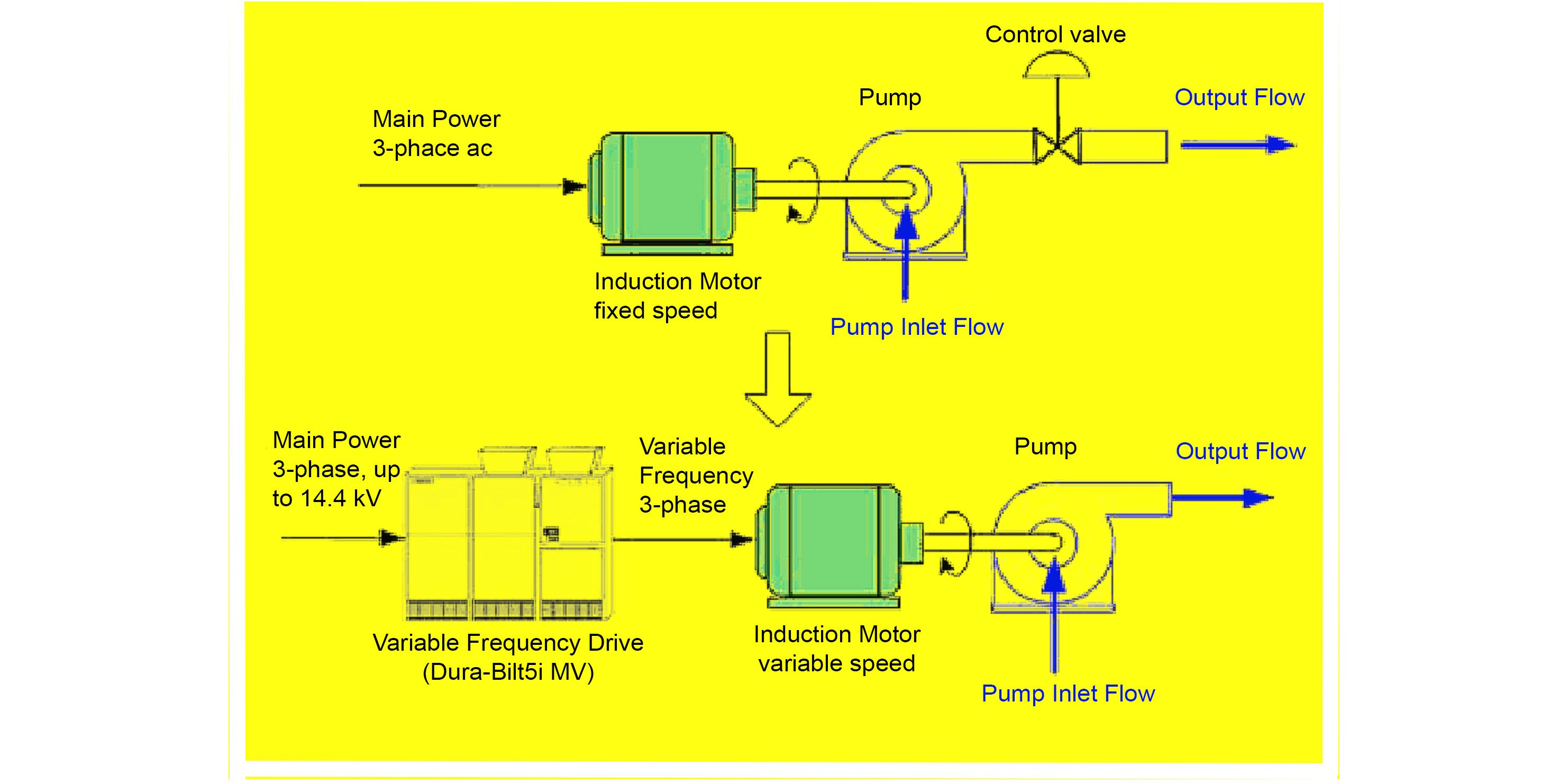
In an industrial environment, electric motors are used for a variety of applications.
These often include pumping water or other fluids, transporting material on conveyors or lifts, or providing motive force to moving parts of a mechanical device. The electric motor dominates the field whenever something needs to move. Regardless of the end user, all these motors will have one thing in common, a motor controller.
A motor controller is a device with the means to turn the motor on and off, provide circuit protection, and serve as a disconnecting means to render the circuit safe during maintenance. Traditionally, this is done with a direct-on-line (DOL) motor starter. A DOL starter installation consists of a branch breaker combined with a DOL motor starter and overload module. In a typical DOL motor starter installation, the branch breaker will serve as short circuit protection, as well as a means of electrical disconnect. The motor starter unit is essentially a large relay with a magnetic coil and high-power contacts held apart by springs. When the motor is called to run, the magnetic coil is energized, pulling in the contacts and bridging the line side to the load side terminals, allowing power to flow. Once the motor starter has contact, electrical power flows out through an overload disconnect module, and then to the electric motor. The DOL motor starter is a well-proven design that is familiar to almost anyone in the industrial space and is still what is found in a majority of applications.
Read More
Topics:
water treatment issues,
water treatment,
water plant,
motors,
pumps
In many water treatment and chemical processes,
it is a requirement to keep track of the pH of the water or product stream. In DeLoach Industries equipment such as degasification systems, or odor control scrubbers, pH measurement is critical to control the chemical reactions happening within the treatment system. PH is an indication of the acidic vs alkaline nature of the fluid. An acidic fluid will have a greater concentration of H+ hydrogen ions, while an alkaline fluid will have a greater concentration of OH- hydroxide ions. This electrochemical nature is used in the construction, reading, and maintenance of electronic pH probes.
PH probes are generally glass and will contain a reference element, and a sensing element. When the pH probe is immersed in the fluid to be measured, the electrical potential difference between the sensing element and the reference element is amplified by electronics and the resulting voltage is used in a calculation to determine pH from differential electron potential. As a pH probe remains in service, ion exchange will slowly change the electrical potential of the sensing element, the reference element, or both. This happens because the hydrogen ions are small enough to travel through the glass sensor body and cause reference potential shifts over time. This is normal behavior for all pH probes and is the reason why pH probes must be periodically calibrated.
Calibration is a process where a pH probe is immersed in a series of standardized stable pH solutions called “buffers”. The standard set of buffers includes a pH 4.0 acidic buffer, a pH 7.0 neutral buffer, and a pH 10.0 alkaline buffer. These buffer solutions are chemically designed to hold a stable pH and are used as a reference for the internal calculations that are done by the pH amplifier or transmitter that interprets the reading taken by the pH probe. As the reference voltage vs actual pH for a mature probe changes, the known buffer solution provides a benchmark for the calculation. Each pH instrumentation manufacturer will have a slightly different method for performing a calibration, but in general, the system will have you step through the buffer solutions while an automated routine makes note of the expected voltage vs calibration voltage at each step. The computation algorithm will use this drift information to re-scale the calculation to re-establish accuracy.
Read More
Topics:
water treatment issues,
water quality,
pH levels of water,
iron oxidation,
water treatment,
advanced treatment solutions,
hydrogen sulfide (H2S),
pH levels,
Alkalinity,
ION Exchange Resin,
carbon dioxide,
gases,
RO system,
Aqua Farming