Clean and safe water is a fundamental requirement for our well-being, yet the increasing presence of PFAS contaminants in industrial water sources remains a significant cause for alarm.
In this blog, we’ll delve into the pressing issue of PFAS contamination in industrial water supplies and shed light on how Reverse Osmosis (RO) technology is a robust safeguard against this concern. We will not only explore the effectiveness of RO in eliminating PFAS but also the distinct advantages it offers over conventional water treatment methods.
The Growing Concern of PFAS in Industrial Water
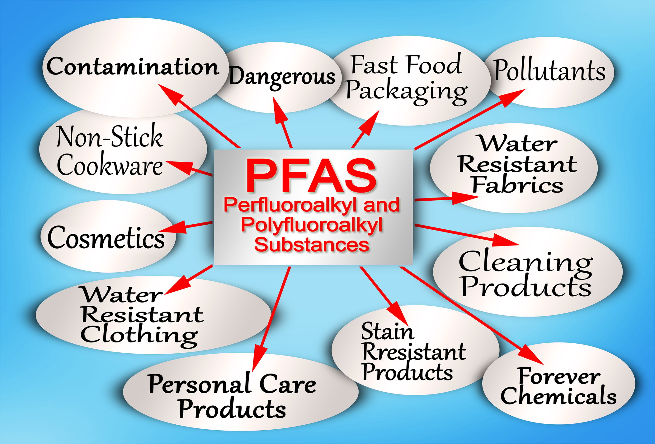
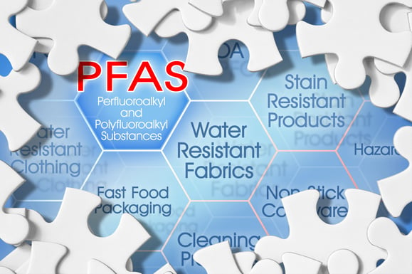
Per- and Polyfluoroalkyl Substances (PFAS) have become a growing concern in industrial water sources. Synthetic chemicals like PFOA and PFOS can stay in the environment and build up, causing significant risks to people and the ecosystem.
Read More
Topics:
water quality,
water treatment,
advanced treatment solutions,
Safe drinking water,
municipal water systems,
DeLoach Industries, Inc.,
Drinking Water,
DeLoach Industries,
removing PFAS & PFOS,
pfas exposure,
health effects of pfas,
exposure to pfas,
water treatment standards,
PFOS,
water purification systems
I will explore the potential risks of exposure to two members of a family of man-made chemicals called PFAS.
These chemicals are PFOA and PFOS, "poly-fluoroalkyl substances."
I will discuss the sources of PFOA and PFOS. These include leaching from industrial sites, the use of consumer products, and food and water contamination.
I will also discuss the exposure pathways of PFOA and PFOS. I will examine the regulations and guidelines for the use of these chemicals. I will also investigate their impact on the environment and various industries.
I will guide long-term human health effects.
This guide covers the potential risks of pfo's and pfoa's. It explains their sources and exposure pathways. It also looks at regulations and guidelines for their usage and impact on the environment and industries.
Introduction to PFOA and PFOS
Read More
Topics:
water treatment issues,
water quality,
water treatment,
advanced treatment solutions,
FDA,
Safe drinking water,
wastewater,
Global,
RO system,
DeLoach Industries, Inc.,
Drinking Water,
PFA's,
DeLoach Industries,
Cosmetics,
make-up,
water process system,
removing PFAS & PFOS,
pfas exposure,
health effects of pfas,
nonstick cookware,
wastewater treatment system,
water treatment standards,
PFOS,
safe drinking water act,
pfoa regulations,
the environmental protection agency,
drinking water standards,
adverse health effects,
water resistant clothing,
environmental safety
If you’ve been following the news, you know a growing problem with PFAS (per- and poly-fluoroalkyl substances) exists.
PFAS, a group of synthetic chemicals in a wide range of products, is causing a growing concern. Despite their widespread use, some PFAS compounds have been found to degrade into potentially harmful byproducts like PFAS-methyl tetrahydrofuran. What's more alarming is that these chemicals have infiltrated our drinking water sources, even in areas with high water tables. This is why it's crucial to understand effective methods for removing PFAS from water. What should you do if you suspect that there’s a problem with your water? Check the source of the water, test it, and treat it if necessary.
Follow these steps to remove PFAS from drinking water.
Test Your Water
Although knowing how to remove contaminants is essential, it’s even more important to understand how to test your water for contamination. A water test kit can help you determine whether there are contaminants in your water and whether they are at a dangerous level. You can purchase water test kits at grocery stores, hardware stores, and online retailers. Generally, these kits come with the standard set of tests for a home water filtration system, but they also often include tests for specific contaminants. Use these tests to determine whether your water is safe to drink. If your water contains contaminants, remove them from your water source. This can be done by digging a more bottomless well, installing a water filtration system, or getting a water purification system. If your water does not contain contaminants, you don’t need to do anything except continue drinking your water.
Check the Source
Understanding the source of your water is a crucial step in addressing contamination. Whether you have a well or a water treatment system, knowing where your water comes from can provide valuable insights. By tracing the water's journey from the source, you can determine if contamination occurs upstream. This knowledge is essential for well owners, who might overlook the significance of understanding their water source. If you find contamination at the source, you can address it immediately, such as reducing the distance between the source and your dwelling or seeking alternative, uncontaminated sources.
Read More
Topics:
water treatment issues,
water quality,
odor control,
water treatment,
advanced treatment solutions,
Chemical Odor,
Safe drinking water,
RO system,
filters,
Filter Media,
residential well water systems,
DeLoach Industries, Inc.,
backwash,
Carbon Filter,
Micron Filter,
Drinking Water,
Clean Water,
Contaminated Water,
Water Source,
Sediment Filter,
PFA's,
Water Test,
Water Test Kit
Water is essential for life, but not all water is safe to drink.
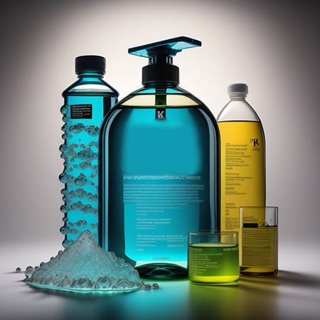
Contaminants like perfluorooctanoic acid (PFOA) and perfluorooctanesulfonic acid (PFOS), collectively known as PFAS, have been a growing concern in our water supply. Fortunately, there's a remarkable solution that often goes unnoticed: carbon absorption filters. Here, we'll explore the technology behind carbon absorption filters, how they effectively trap PFAS and their numerous benefits in water treatment.
Understanding Carbon Absorption Technology
Before delving into how carbon filters combat PFAS, let’s review the fundamentals of carbon absorption technology. Activated carbon, the hero in this story, is an incredibly porous material with a vast surface area, typically derived from sources like coconut shells, wood, or coal. This porous structure is what makes activated carbon ideal for trapping contaminants.
1. Activated Carbon's Structure: Think of activated carbon like a sponge, but not just any ordinary sponge – it's a super sponge! At a microscopic level, it's filled with tiny pores and holes, creating a vast and intricate network. Imagine walking through a maze with endless twists and turns – that's what the structure of activated carbon looks like. And why does this matter? Because all those nooks and crannies provide a massive surface area. It's like having a big, open field instead of a cramped room. This extra space is perfect for grabbing onto molecules, kind of like how Velcro sticks to fabric. This process is called adsorption, where molecules stick to the surface of the carbon rather than getting soaked up inside like a regular sponge.
2. Adsorption vs. Absorption: Let's clear up some confusion between two similar-sounding words. Absorption is like when a sponge soaks up water – it goes inside the sponge. But adsorption is different; it's all about what happens on the surface. Imagine you're playing with magnets. When they attract and stick together, that's like adsorption. Activated carbon is a magnet for contaminants. It doesn't suck them in like a vacuum; instead, it attracts them and sticks them onto its surface, where they stay put. So, while absorption is about taking things in, adsorption is about grabbing onto things on the outside.
3. Adsorbent Specificity: One of the remarkable features of activated carbon is its remarkable versatility and ability to adsorb a wide range of contaminants, including volatile organic compounds (VOCs), which are harmful chemicals emitted from products like paints and cleaning supplies, chlorine, commonly found in water disinfection processes, and, most importantly, PFAS, notorious for their widespread presence in water sources and resistance to degradation, making activated carbon an indispensable tool in combating environmental pollution.
Read More
Topics:
water quality,
water treatment,
advanced treatment solutions,
Safe drinking water,
municipal water systems,
DeLoach Industries, Inc.,
Drinking Water,
DeLoach Industries,
carbon filters,
removing PFAS & PFOS,
pfas exposure,
health effects of pfas,
exposure to pfas,
water treatment standards,
PFOS,
drinking water standards,
forever chemicals,
water purification systems,
carbon absorption
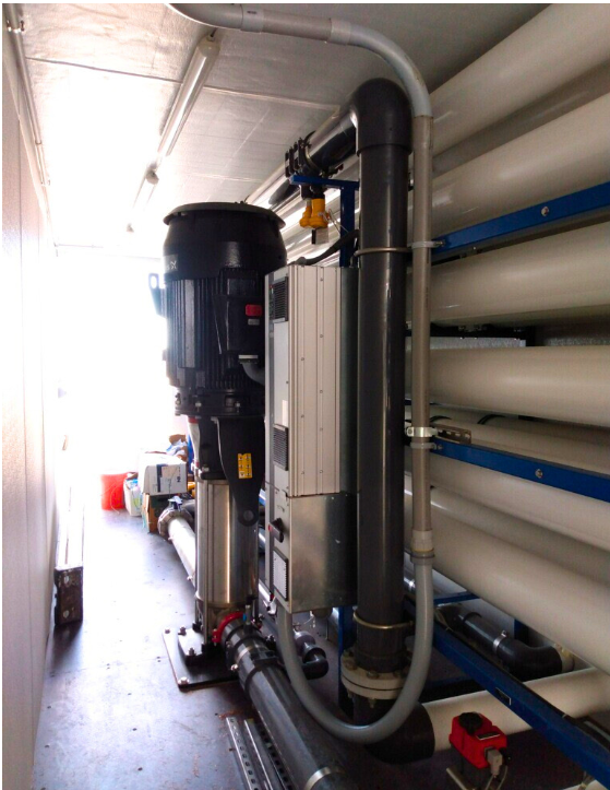
In recent years, PFOA and PFOS, commonly known as "forever chemicals," have raised concerns among municipalities, food and beverage industries, and commercial facilities in the USA and around the globe. These synthetic chemicals, which never break down and pose significant health risks, have been detected in water, food supplies, and even bottled purified water. As new EPA regulations take effect in 2024, industries are searching for effective and cost-efficient methods to remove these hazardous substances from their water supply. Fortunately, advanced water purification technologies such as microfiltration, ultrafiltration, and reverse osmosis can address these challenges.
Read More
Topics:
water quality,
advanced treatment solutions,
Safe drinking water,
RO system,
municipal water systems,
DeLoach Industries, Inc.,
Drinking Water,
DeLoach Industries,
reverse osmosis,
water process system,
removing PFAS & PFOS,
pfas exposure,
health effects of pfas,
exposure to pfas,
water treatment standards,
PFOS,
safe drinking water act,
the environmental protection agency,
drinking water standards,
forever chemicals,
water purification systems,
microfiltration and ultrafiltration,
potable water,
membrane technology,
types of membranes,
flat sheet,
spirally wound
Computer-aided design systems and the advancements in water treatment solutions.
These unique cad design tools have allowed our society to progress rapidly. There have been drastic improvements within the CAD world. CAD computer-aided design programs became commercially available in 1964 when large companies like IBM, GM, and Lockheed Martin began leveraging computerized graphical display systems. These foundational programs are still the basis for some of the most widely used programs.
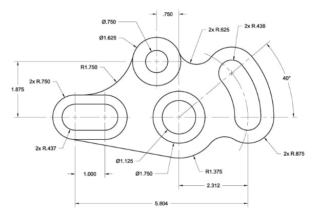
To this day, 2D CAD is used regularly throughout multiple industries, including Water Treatment, Municipal, Food & Beverage, Commercial, and Pisciculture. While 3D CAD has many advantages over traditional 2D, it is essential to consider your product and its end user. All fabrication drawings, from structural to electrical, are read on 2D paper.
Architects and civil engineers use 2D to convey their ideas to cities, companies, and private parties. Electrical engineers create complex wiring diagrams in 2D only. Due to the clarity provided and adhering to standards followed worldwide.
Figure: Example of a 2D CAD Drawing.
On the other hand, the 3D CAD design program is a young technology that has provided amazing breakthroughs in workflow increases and cost savings. 3D modeling became widely accessible in the late 1980s. It became a challenge that required engineers to rewire their brains to create models in the third dimension. 3D CAD software has two main categories:
- Parametric modeling
- Direct modeling
Direct modeling: grants the user flexibility by allowing them to define and capture geometry quickly without concentrating on dimensions. Direct modeling is perfect for prototyping, considering how agile the method is. A simple analogy would be to imagine working with modeling clay. Rather than measuring, you push and pull until you are satisfied with the geometry.
Read More
Topics:
design intent,
2D CAD Drawing,
3D CAD Software,
3d modeling,
computer-aided design,
parametric cad,
type of modeling,
parametric modeling
PFOA and PFOS are man-made chemicals used in various products to simplify life.
Forever chemicals, also known as synthetic chemicals called PFAS, have gained recognition. Scientists created these chemicals to make products resistant to water, stains, and sticking. The United States initially utilized them in the 1950s.
DuPont introduced Teflon in the 1950s to help Americans have nonstick cookware and make their lives easier. Americans and people from other countries liked this new improvement and soon used these substances in many different products.
These chemicals are resistant to water and lipids, so they don't break down and last a long time in the environment.
Over time, companies have used these chemicals in manufacturing various products, such as firefighting foam, food packaging, and cosmetics. As a result, these chemicals have entered the air, water, soil, and food production. They discontinued the use of PFAS and their other compounds in the mid-1970s.
People believe that contamination has affected more than 7000 metric tons of Fluorochemicals. PFOAs and PFOS, which can cause various health problems, have exposed many Americans and people in the USA.
PFOA chemicals contaminated 1% of public drinking water supply systems in 2016. The EPA did not regulate safe levels of PFOA and PFOS in drinking water systems for many years.
Read More
Topics:
water quality,
advanced treatment solutions,
pH levels,
Safe drinking water,
RO system,
particulate matter,
Filter Media,
municipal water systems,
DeLoach Industries, Inc.,
Drinking Water,
Clean Water,
PFA's,
DeLoach Industries,
nylon,
Cosmetics,
reverse osmosis,
water process system,
removing PFAS & PFOS,
pfas exposure,
health effects of pfas,
exposure to pfas,
nonstick cookware,
food packaging,
water treatment standards,
PFOS,
safe drinking water act,
pfoa regulations,
the environmental protection agency,
drinking water standards,
water resistant clothing,
environmental safety,
forever chemicals
In modern industrial water treatment, advancements in technology and processes have revolutionized the way contaminants are removed from water.
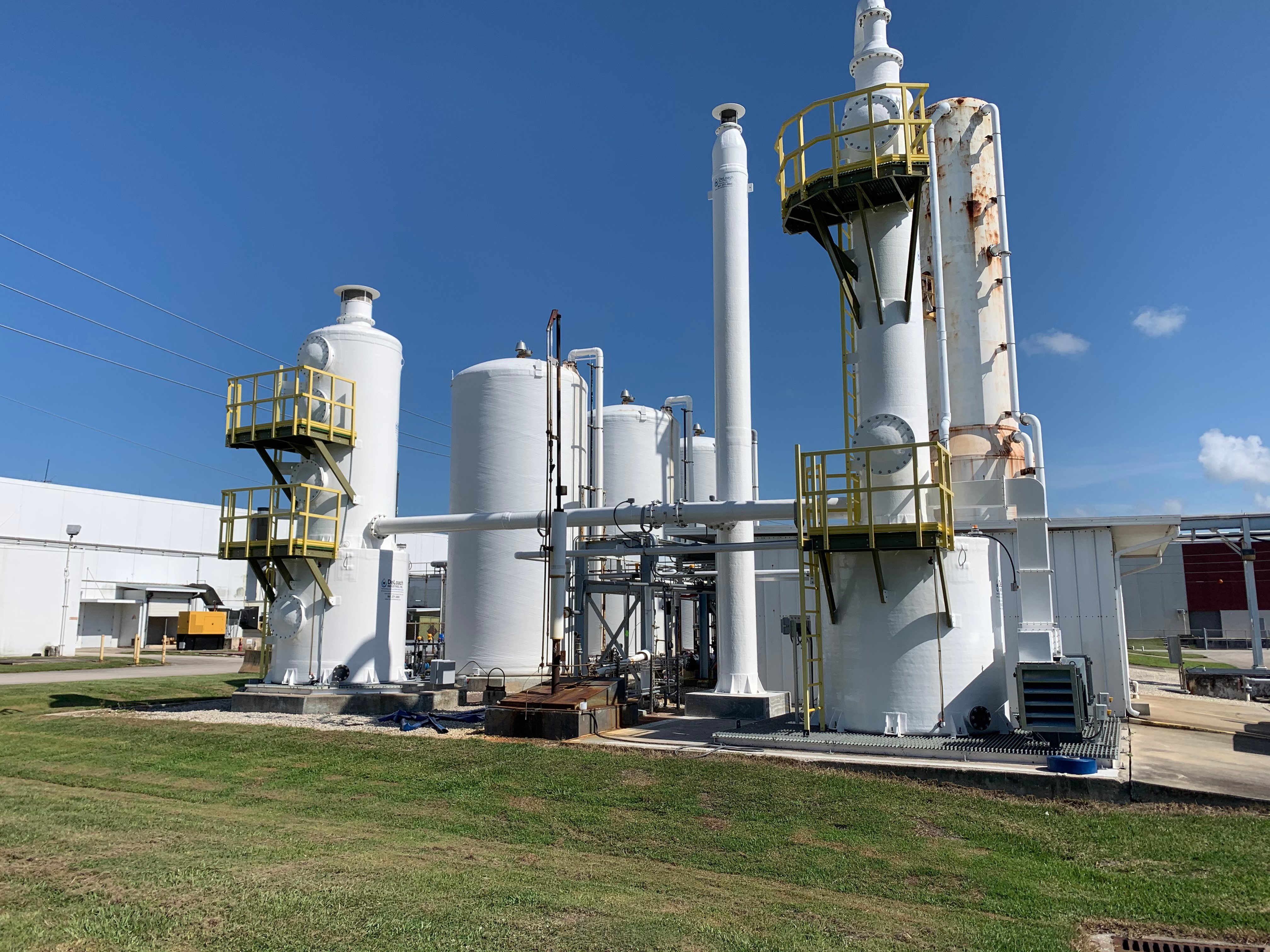
This blog explores the integration of NSF/ANSI 61 certified systems, artificial intelligence in water treatment, and cutting-edge processes such as decarbonation and degasification. We'll also discuss the key differences between forced draft and induced draft degasification towers, helping you make informed decisions while designing your Industrial Water Treatment System.
-
NSF/ANSI 61-Certified Water Treatment Systems: To ensure the safety and quality of water treatment equipment, NSF/ANSI 61 certification has become a crucial standard. This certification verifies that materials and components used in water treatment systems comply with health and safety requirements. When selecting a water treatment solution, opting for NSF/ANSI 61 certified systems guarantees peace of mind and adherence to the highest industry standards.
-
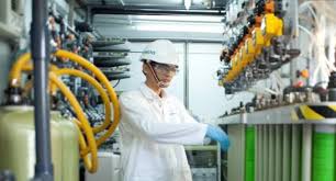
Harnessing Artificial Intelligence in Water Treatment: Artificial intelligence (AI) has penetrated various industries, and water treatment is no exception. Integrating AI into water treatment processes allows for more efficient and optimized operations. AI-driven systems can monitor water quality in real-time, predict system failures, optimize chemical dosing, and reduce energy consumption. By leveraging AI technologies, water treatment facilities can enhance their overall performance and streamline resource utilization.
-
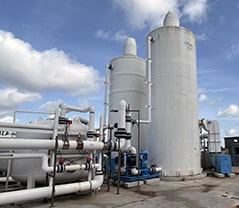
Decarbonation and Degasification Systems: Decarbonation and degasification are essential processes in industrial water treatment, particularly in pH levels in water and the ability to control removing the contaminants. These processes target the removal of carbon dioxide (CO2) and other dissolved gases from water to improve its quality. Two key systems used for this purpose are the decarbonator and aeration system.
Read More
Topics:
degasification,
advanced treatment solutions,
biological scrubber,
NSF/ANSI 61,
Chemical Odor,
Decarbonation,
Safe drinking water,
De-Aeration,
decarbonator,
degasifier,
degassed water,
ansi61,
nsf/ansi61,
Deagasification,
decarbonation of water,
DeLoach Industries, Inc.,
Drinking Water,
Industrial Odor Control,
DeLoach Industries,
contaminants,
process system,
safe drinking water act,
drinking water standards,
environmental safety,
air emissions,
Forced Draft,
Induced Draft
Degasification and decarbonation are essential processes in water treatment that play a crucial role in improving water quality.
Read More
Topics:
degasification,
hydrogen sulfide (H2S),
Decarbonation,
dissolved gases,
decarbonator,
degasifier,
gases,
carbonic acid,
H2S Degasifier,
co2 dissolved in water,
degassed water,
decarbonation of water,
DeLoach Industries, Inc.,
hydrogen sulfide molar mass,
DeLoach Industries,
carbon filters,
removing hydrogen sulfide in water,
hydrogen sulfide gas,
dissolved oxygen
Requires an application commonly referred to as either “Degasification” or "Decarbonation" and it requires the use of a piece of water treatment equipment called either a “degasifier” or a “decarbonator”.
Both of these are similar in nature and are designed for Carbon Dioxide (CO2) removal from the incoming water. A properly designed decarbonator can remove 99.99% of the free carbon dioxide gas that is present in the water stream. One of the primary reasons for utilizing a decarbonator or degasifier for the removal of carbon dioxide gas is the raise the pH of the water without the need to add caustic. resulting in high-purity water.
The other reason is the remove the CO2 prior to treating the water with Ion Exchange which utilizes Anion or Cation resins to reduce the regeneration cycles for the resin beds. High concentrations of CO2 consume the ion charge within the resins and require more frequent regeneration cycles. The difference between anion and cation resins is that one is positively charged (anion) and the other is negatively charged (cation), cation resins, attract positive ions with their negative charge.
The term decarbonation describes the process of the removal of suspended gas or the conversion of carbonic acids into free Carbon Dioxide. Carbonic Acid (H2CO3) is stable at normal ambient anhydrous conditions. However, Carbonic Acid decomposes when not stable and in the presence of any water molecules to form carbon dioxide (CO2). The Carbonic acid breaks down when present in water and it is converted to a gas based upon certain conditions. It is common to have CO2 present in water requiring a decarbonation process when utilizing certain types of water filtration such as membrane filtration with reverse osmosis or it can be present when the need to adjust pH is required. When removing (CO2) the process is often referred to as “Decarbonation”, when removing (H2S) Hydrogen Sulfide the process is often referred to as “Degasification”.
Read More
Topics:
water treatment issues,
degasification,
pH levels of water,
aeration,
iron oxidation,
water treatment,
water plant,
bicarbonate,
hydrogen sulfide (H2S),
pH levels,
Decarbonation,
ION Exchange Resin,
dissolved gases,
De-Aeration,
wastewater,
carbon dioxide,
oxygen,
decarbonator,
degasifier,
gases,
carbonic acid,
H2S Degasifier